

Slug Catcher
Slug Catcher
1. Slug Flow
Slug flow can occur in multiphase flows, especially in natural gas production processes. Factors such as pipeline cleaning, the addition of new wells, and changes in terrain causing variations in pipeline elevation can lead to significant slug flow due to changes in gas-liquid flow parameters. The figure below illustrates a typical case of slug flow caused by pipeline topography (undulations). It manifests as sudden large fluctuations in flow and pressure, impacting the normal operation of oil and gas field production equipment (separators are usually designed for stable flow and operating conditions). Figure 1(a) shows one way slug flow can occur, while Figure 1(b) depicts the pressure fluctuations in the pipeline due to slug flow. Figure 1(c) presents the instantaneous gas and liquid flow rate changes in a pipeline at a Saudi oilfield measured by a multiphase flowmeter, clearly indicating that the pipeline is experiencing slug flow conditions.
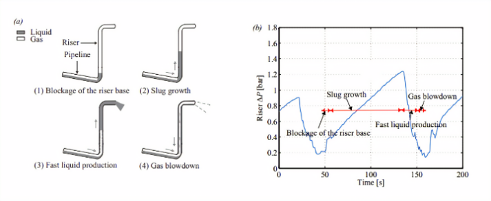
Figure 1, Slug Flow Generation and Impact. The left part of Figure (a) shows that due to pipeline elevation, liquid accumulates at the bottom of the pipeline, gradually blocking the passage and preventing gas flow. As the gas is compressed and pressure builds up, it eventually reaches a critical point, pushing the liquid at high speed. The right part of Figure (b) shows how pipeline pressure changes over time, increasing from around 0.2 bar to about 1.2 bar as the liquid blockage is cleared.
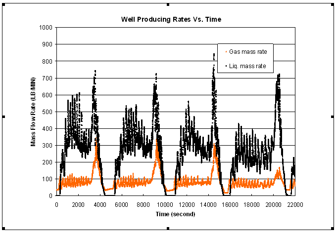
Figure 1(c), Flow rate variation over time under slug flow conditions (data from VREIT MERSEY multiphase flowmeter).
2. Impact of Slug Flow on Oil and Gas Field Surface Processing Facilities
Severe slug flow can cause significant fluctuations in pressure and flow, disrupting production separation equipment. In severe cases, it can prevent normal separation functions and damage equipment or pipelines. Therefore, severe slug flow must be managed to minimize its impact on production separation systems and ensure system stability.
3. Methods for Handling Slug Flow
The goal of handling slug flow is to mitigate the significant pressure and flow fluctuations caused by severe slug flow, providing a more consistent pressure and flow to downstream equipment. Common methods include vessel-type, pipeline-type (finger-type), and combinations of pipeline and vessel. Vessel-type is generally used for slugs less than 100 cubic meters and low-pressure conditions. Pipeline-type is more economical for high-pressure and large-slug situations. The following sections provide examples of typical methods and images.
Figures 2 and 3 show the combination of pipeline-type slug catchers and cylindrical cyclonic separators. This combination is compact and structurally simple, replacing most vessel-type slug catchers. There are over several dozen successful application cases.
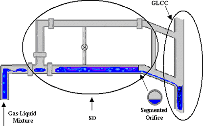
Figure 2, Pipeline-type Slug Catcher with Cylindrical Cyclonic Separator
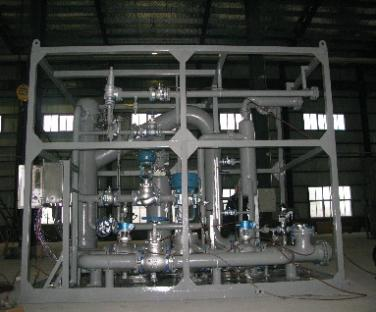
Figure 3, Pipeline-type Slug Catcher (GLCC) on a CNOOC Platform, VREIT MERSEY
Figure 4 is a vessel-type slug catcher. It has a large volume and high cost but offers greater storage capacity compared to GLCC pipeline types. It is suitable for low-pressure applications and those requiring storage.
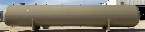
Figure 4, Vessel-type Slug Catcher
Figures 5 and 6 illustrate combinations of pipeline and vessel types. The pipeline-type high-energy separator GLCC provides buffering and gas-liquid separation, while the vessel handles storage and oil-water separation. This combination is particularly advantageous for high-pressure applications.
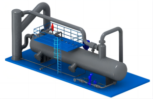
Figure 5, Combination of Pipeline and Vessel Types
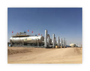
Figure 6, Application of Pipeline and Vessel Combination, VREIT MERSEY
Figure 7 is a schematic diagram of a finger-type (pipeline-type) slug catcher (TFG). It relies on a group of pipelines for separation and storage, occupying a large area. However, it is easy to manufacture and assemble on-site, making it suitable for applications with large throughput and relatively high pressure.
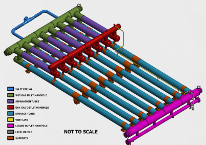
Figure 7, Finger-type (Pipeline-type) Slug Catcher (TFG)
Compared to traditional vessel-type slug catchers, GLCC and GLCC-vessel combinations are smaller and less expensive, ensuring stable system operation and receiving widespread application and positive feedback.
Finger-type slug catchers are less costly than vessel-type slug catchers and are widely used in applications with large slug flows and high pressure.
4. Flow Structure Design for Finger-type Slug Catchers
Conventional separator design methods, refined over many years, are well-established. However, these methods do not extend to the design of finger-type slug catchers because the operating flow regimes and conditions of finger-type slug catchers differ significantly from conventional separators. Finger-type slug catchers use parallel, slightly inclined pipes of the same diameter for separation. Even in the Stokes separation region, different correction formulas are required. Additionally, since the main function of a slug catcher is to separate gas and liquid under severe slug flow conditions, which are non-steady-state, this aspect must also be considered in the structural design. Key points in the design of finger-type slug catchers include:
1) Non-steady-state, characteristics of predicted extreme slug flow, and range definition;
2) Design calculation methods under non-steady-state conditions;
3) Structural design under non-steady-state conditions.
Traditionally, the design of finger-type slug catchers has been experience-based. Currently, it is evolving towards a comprehensive design approach combining multiphase flow analysis and non-steady-state multiphase flow simulation. The aim is to avoid overdesign and reduce construction costs. Since separation and buffering occur in pipelines, careful analysis and design, as well as simulations, are required from the inlet to each branch pipeline. Key elements include:
1) Primary distribution design of the inlet section;
2) Distribution manifold design of the inlet section (to reduce maldistribution);
3) Design of the slug flow (gas-liquid) separation zone (coarse separation to protect the gas separation zone);
4) Design of the gas separation zone;
5) Design of the oil-water separation zone.
Contact Information : Ye Zilong Phone: +86-133-8667-7776
Email: zilong.ye@vtechcn.com
Contact Information : Wang Jianrong Phone: +86-133-2612-8487
Email: jianrong.wang@vtechcn.com
1. Slug Flow
Slug flow can occur in multiphase flows, especially in natural gas production processes. Factors such as pipeline cleaning, the addition of new wells, and changes in terrain causing variations in pipeline elevation can lead to significant slug flow due to changes in gas-liquid flow parameters. The figure below illustrates a typical case of slug flow caused by pipeline topography (undulations). It manifests as sudden large fluctuations in flow and pressure, impacting the normal operation of oil and gas field production equipment (separators are usually designed for stable flow and operating conditions). Figure 1(a) shows one way slug flow can occur, while Figure 1(b) depicts the pressure fluctuations in the pipeline due to slug flow. Figure 1(c) presents the instantaneous gas and liquid flow rate changes in a pipeline at a Saudi oilfield measured by a multiphase flowmeter, clearly indicating that the pipeline is experiencing slug flow conditions.
Figure 1, Slug Flow Generation and Impact. The left part of Figure (a) shows that due to pipeline elevation, liquid accumulates at the bottom of the pipeline, gradually blocking the passage and preventing gas flow. As the gas is compressed and pressure builds up, it eventually reaches a critical point, pushing the liquid at high speed. The right part of Figure (b) shows how pipeline pressure changes over time, increasing from around 0.2 bar to about 1.2 bar as the liquid blockage is cleared.
Figure 1(c), Flow rate variation over time under slug flow conditions (data from VREIT MERSEY multiphase flowmeter).
2. Impact of Slug Flow on Oil and Gas Field Surface Processing Facilities
Severe slug flow can cause significant fluctuations in pressure and flow, disrupting production separation equipment. In severe cases, it can prevent normal separation functions and damage equipment or pipelines. Therefore, severe slug flow must be managed to minimize its impact on production separation systems and ensure system stability.
3. Methods for Handling Slug Flow
The goal of handling slug flow is to mitigate the significant pressure and flow fluctuations caused by severe slug flow, providing a more consistent pressure and flow to downstream equipment. Common methods include vessel-type, pipeline-type (finger-type), and combinations of pipeline and vessel. Vessel-type is generally used for slugs less than 100 cubic meters and low-pressure conditions. Pipeline-type is more economical for high-pressure and large-slug situations. The following sections provide examples of typical methods and images.
Figures 2 and 3 show the combination of pipeline-type slug catchers and cylindrical cyclonic separators. This combination is compact and structurally simple, replacing most vessel-type slug catchers. There are over several dozen successful application cases.
Figure 2, Pipeline-type Slug Catcher with Cylindrical Cyclonic Separator
Figure 3, Pipeline-type Slug Catcher (GLCC) on a CNOOC Platform, VREIT MERSEY
Figure 4 is a vessel-type slug catcher. It has a large volume and high cost but offers greater storage capacity compared to GLCC pipeline types. It is suitable for low-pressure applications and those requiring storage.
Figure 4, Vessel-type Slug Catcher
Figures 5 and 6 illustrate combinations of pipeline and vessel types. The pipeline-type high-energy separator GLCC provides buffering and gas-liquid separation, while the vessel handles storage and oil-water separation. This combination is particularly advantageous for high-pressure applications.
Figure 5, Combination of Pipeline and Vessel Types
Figure 6, Application of Pipeline and Vessel Combination, VREIT MERSEY
Figure 7 is a schematic diagram of a finger-type (pipeline-type) slug catcher (TFG). It relies on a group of pipelines for separation and storage, occupying a large area. However, it is easy to manufacture and assemble on-site, making it suitable for applications with large throughput and relatively high pressure.
Figure 7, Finger-type (Pipeline-type) Slug Catcher (TFG)
Compared to traditional vessel-type slug catchers, GLCC and GLCC-vessel combinations are smaller and less expensive, ensuring stable system operation and receiving widespread application and positive feedback.
Finger-type slug catchers are less costly than vessel-type slug catchers and are widely used in applications with large slug flows and high pressure.
4. Flow Structure Design for Finger-type Slug Catchers
Conventional separator design methods, refined over many years, are well-established. However, these methods do not extend to the design of finger-type slug catchers because the operating flow regimes and conditions of finger-type slug catchers differ significantly from conventional separators. Finger-type slug catchers use parallel, slightly inclined pipes of the same diameter for separation. Even in the Stokes separation region, different correction formulas are required. Additionally, since the main function of a slug catcher is to separate gas and liquid under severe slug flow conditions, which are non-steady-state, this aspect must also be considered in the structural design. Key points in the design of finger-type slug catchers include:
1) Non-steady-state, characteristics of predicted extreme slug flow, and range definition;
2) Design calculation methods under non-steady-state conditions;
3) Structural design under non-steady-state conditions.
Traditionally, the design of finger-type slug catchers has been experience-based. Currently, it is evolving towards a comprehensive design approach combining multiphase flow analysis and non-steady-state multiphase flow simulation. The aim is to avoid overdesign and reduce construction costs. Since separation and buffering occur in pipelines, careful analysis and design, as well as simulations, are required from the inlet to each branch pipeline. Key elements include:
1) Primary distribution design of the inlet section;
2) Distribution manifold design of the inlet section (to reduce maldistribution);
3) Design of the slug flow (gas-liquid) separation zone (coarse separation to protect the gas separation zone);
4) Design of the gas separation zone;
5) Design of the oil-water separation zone.
Contact Information : Ye Zilong Phone: +86-133-8667-7776
Email: zilong.ye@vtechcn.com
Contact Information : Wang Jianrong Phone: +86-133-2612-8487
Email: jianrong.wang@vtechcn.com
Products & Solutions
- Metering Module
- Wellhead Monitoring Skid
- Single Well Metering Ski
- Oil-Water Separation Mem
- Slug Catcher
- Vane Type Separator
- Filter cartridge
- GLCC Desander System
- Water Treatment Module
- Micro-Bubble Flotation T
- Hyperbolic hydrocyclone
- Gas dissolution pump
- Mobile Electrocoagulatio
- Mechanical foam eliminat
- Chemical Injection Skid